Hi there. I mentioned hard disk hardware in the previous article. This article will be a bit more software oriented as much as an article about interrupts and IO ports could be. Let's start with the most fundamental data structure of hard disks.
Master Boot Record (MBR)
MBR is a structure in the first sector of each hard disk, holding partitioning scheme and containing some code. During a power-on of a computer, BIOS takes the execution and after it is done with its job, it reads the first sector from one of the accessible storage devices according to the boot sequence setting in CMOS. This process has not changed much since 1980s. If the boot medium is a floppy disk, that first sector is the boot sector, if it is a hard disk then the first sector is MBR. For BIOS, boot sector and MBR has no difference. BIOS only copies the first sector of the first available drive to memory location 0000:7C00 and makes a far jmp here to boot. Obviously, it has nothing to do with protected mode yet, since I was talking about 80s and using real mode addressing.
The code in MBR determines which partition is set for booting, reads the first sector of that partition to memory and branches there. MBR keeps disk partitions in a table.
I used
HxD disk editor throughout this article to read MBR under Windows. I ran HxD as administrator, selected "Open Disk" (Ctrl + Shift + D) and then selected one of the physical disks. I recommend to "Open as Readonly".
Linux users are lucky because following command is sufficient:
sudo dd if=/dev/sda count=1 bs=512 | hexdump -C -v
While I was trying to learn assembly, being able to view MBR after 3-4 months was a great success for me. I am mentioning a blast from the past.
The screenshot from HxD is above. I colored the image to make easy to distinguish. The red area is code, blue area is partition table and the green area is MBR signature. Even though the sector is intact, BIOS will not boot without that 0x55 0xAA signature. So why this number? Because it is (0101
0101 1010 1010)
2.
Same output under Linux is here:
Since GRUB is installed on both machines, both outputs above contain GRUB MBR code. Before examining the code, let's take a look at the partition table colored in blue. In the example I gave with debug.exe in the previous article, same code and signature can be easily seen.
Partition Table
Partition table is a 4*16 byte field starting from the offset 01BEh of MBR. There is a 16-byte record for each primary partition.If I exclude extended partitions for now, according to the previous statement, there can be 4 primary partitions at most. The table below shows the structure of the records:
| Offset | Size
| Description |
|---|
| 0x00 | byte | Bootable Flag |
| 0x01 | 3 byte | Starting CHS address |
| 0x04 | byte | System ID
|
| 0x05 | 3 byte | Ending CHS address
|
| 0x08 | dword | Starting LBA address
|
| 0x0C | dword | Total sectors in partiton
|
Bootable flag indicates that, it will be booted from that partition at startup. There can be
one and only one partition with bootable flag set in each MBR. If this value is 00h, that means the partition is not bootable. If it is 80h, that means the partition is bootable but some MBR code checks only its seventh bit. Thus the values between [01h, 7Fh] are invalid.
I skip CHS address part shortly right now and come back later.
Although system ID field specifies the type of filesystem used in that partition, this byte is not that important. Some OS and OS installers often do not check this field. This field has also no standard. There were some values used by Microsoft and IBM in 80s. During minix and linux were developed, the values that are not used by Microsoft or IBM at that time, were randomly chosen as their ID number and subsequently de facto standardized. Detailed information about this and the list of these IDs are available on Wikipedia:
https://en.wikipedia.org/wiki/Partition_type The starting LBA address field is the value obtained by translating starting CHS address into LBA. The purpose of the total number of sectors field can be understood from its name. Multiplying this value with 512 bytes, gives the size of the partition but this value is its raw space not the formattable space. I will explain the difference of the two in the boot sector article.
CHS addresses are stored with a complex scheme. The first byte of this three byte field is the head number. The low six bits of the second byte hold the sector number. The third byte is the low eight bits of cylinder number. And the high two bits of second byte also hold two high bits of cylinder number (which makes it 10 bits in total). I tried to visualise this below:
| 1. Byte |
2. Byte |
3. Byte |
| H7 | H6 |
H5 | H4 |
H3 | H2 |
H1 | H0 |
C9 | C8 |
S5 | S4 |
S3 | S2 |
S1 | S0 |
C7 | C6 |
C5 | C4 |
C3 | C2 |
C1 | C0 |
Okay, does it sound familiar? Yes, int 13h. First byte to DH, second to CL and third to CH, et voila. Fits perfectly.
In the previous article, I wrote that CHS addressing is insufficient for hard disks over 8 GB:
With a more optimistic approach, without fuss; assuming that the MBR code does not need end CHS address because to load the boot sector of a partition only starting CHS address is sufficient, it can be concluded that bootable disk partitions can only be created within the first 8 GB of hard disks. It is impossible to boot from partitions beyond the 8 GB limit using CHS!
OK, how can a partition be created beyond 8 GB? There is a 32-bit sized starting LBA address field. If a boot loader checks this field, instead of CHS, LBA supports 232
* 512 byte = 2 TB, it can boot from partitions in first 2 TB space. Additionally, since the total number of sectors in partition field has also 32 bits, a 2 TB partition can be created just before the end of this 2 TB limit and thus MBR can still be used on disks up to 4 TB, in theory. I am saying "in theory" becuase there is no guarantee that a 25 year old MBR code will run successfully with these extreme values.
I have added the screenshot with debug.exe from the previous article below again. Let's try to understand the meaning of the bytes here:
80 | 01 01 00 | 06 | 0F 3F FF | 00 00 00 C1 | EF 03 00 00
00 | 00 41 00 | 06 | 0F 7F FF | 00 F0 03 00 | 00 F0 03 00
There are two disk partitions above. First one is bootable. Both system IDs (06h) correspond to FAT16. CHS addresses of the first partition are (0, 1, 1) - (255,
15, 63) starting from 63rd sector and 257 985 sectors long. CHS addresses of the second partition are (256, 0, 1) - (511, 15, 63) starting from sector 258 048 and 258 048 sectors long.
Why is this table so important? If I had been creating my own OS which will run in a computer alone, it has no importance at all. I can ignore all of this, say that I have designed a better table and going to use mine. But since all other OS developers have agreed on this structure and if I use my own partition table, my OS cannot be compatible with others.
Damn the Partition Table and Let's Write Code...Well yes, I still could not start writing code but I will start giving examples in this section. First, I created two VMs for testing. In previous article, I had installed DOS6.22 on one of the VMs in VirtualBox for the first example. 32MB of RAM and a 500MB hard disk are enough for this VM. This machine comes with a network card after it is created. I set it host-only (Settings ->
Network
-> Enable Network Adapter, Attached to: Host-only Adapter). DOS floppy images can be found on Internet. I also used Damn Small Linux (DSL) iso. Live distros like Ubuntu, Knoppix etc. do not run on 32 MB RAM. DSL iso is just 50MB. Since it is no longer developed it can be downloaded either
here or
here.
TinyCore Linux, which is the closest alternative to DSL, has an iso of 14MB but runs on 64 MB RAM.
After I booted the machine with the first MS-DOS installation disk, setup asks to create a partition but I quit setup and manually created a partition with fdisk:
1 - 1 - N - 25% - Esc
After doing that, the warning on the screen informs me that "No partitions are set active". This means, there is no partition whose first byte (bootable flag) is 80h. This warning will disappear after pressing
2 - 1 - Esc (setting partition active). Afterwards, when I tried to create another primary partition, I got an error. Unfortunately, fdisk cannot create more than one primary partition. An extended partition can be created but I will explain extended partitions at the end of this article. I pressed Esc to exit the main menu, removed the floppy disk and booted the machine with DSL. By the way, after disk partitions are created or deleted, DOS is unable to recognize them unless it is restarted.
I found the partition I created, by running sudo fdisk -l command in terminal and I added another partition by running following commands:
sudo fdisk /dev/hda
n - p - 2 - (Enter) - 512
t - 2 - 6
p
w
After powering my virtual machine again with DOS floppies, OS recognized and formatted C: and D:. A standard Microsoft installation is completed by pressing Enter key repeatedly, removing previous floppy disk and inserting next one during the installation. And by the way; a warning to those who forgot the last floppy disk in the drive and got "Non-system disk error" after reboot: In the past, when somebody boots a computer with a floppy disk whose boot sector is infected with a boot virus, the virus writes itself into the memory during the boot, shows this error and waits for the user to press a key to spread further. To avoid this, it would be necessary to restart the computer instead of pressing a key. In order to clean the boot viruses, the MBR code of harddisks could be rewritten with
fdisk /mbr command. Nowadays, it can be used to remove GRUB installation from harddisk.
After installing DOS, I checked the MBR again using debug.exe:
I booted the machine again with DSL. Machine IP address should appear on the right of the screen. I will use this IP to copy files from my host to VM. Since my host runs linux, I can copy files easily with scp. Windows users have to start sshd in VM by following: DSL
-> System -> Daemons -> ssh -> start. Then WinSCP can be used (Cygwin works too).
The file, I am going to copy, is the disk editor in
Norton Utilities package. There are two different versions of disk editor with same file name DISKEDIT.EXE. First one is from Norton Utilities v8.0 (1994) release and the other comes in Norton Utilities 2000 release. First one supports CHS and second one supports LBA. The file from Norton 2000 release is bigger in size (about 600K). It is really practical to work with a disk editor, therefore those who can find this file, should consider him-/herself lucky. (Disclaimer: If these files are still copyrighted, downloading them could violate the law).
I wrote the disk editor files to the disk of VM, restarted the computer once again and I started the editor. I listed the disks by pressing Alt+D. I selected "Physical Disks" as type and opened the harddisk. It showed the sectors like HxD. I selected "View as Partition Table" under View menu (or pressed F6), and all the information, I had to decode manually in previous section, has appeared. Disk editor will help very much for the boot sector and FAT. Therefore, it is useful to keep it in disk.
If you have iso file of Norton Utilities, you have to install CD drive in DOS. Readers who haven't used DOS before, may be surprised at the necessity of installing a CD drive but well those were the days. I will explain the installation in a separate article and give its link here.

According to the screenshot, second partition ends at the end of 511th cylinder. By pressing Alt+I and selecting "Drive Info" in this menu, the editor shows the properties of the hard disk (next figure).
Drive Number: 80 Hex (First physical disk)
Int 13x: Yes (BIOS supports LBA)
Sides: 16 (Heads)
Tracks: 1015 (Cylinders)
Sectors/track: 63
Total Sectors: 1 024 000
This information can also be retrieved using
Int 13h/08 subroutine:
Number of cylinders is 3F6h, number of sectors per cylinder is 3Fh and number of heads is 0Fh. The return values in the registers can be interpreted using Ralf Brown's interrupt list (
Int13h/08). As it can be seen, DL = 02 in the output above, because I had added another hard disk to the machine at that time for testing.
Now, I will write "denizyildizi" (a totally random word meaning starfish in Turkish) into a random sector of the disk. Let me write to CHS 600,0,1. This address corresponds to 604 800 in LBA (using the formula to convert from CHS to LBA in previous article). I opened the disk editor, pressed Alt+P and typed LBA address in the dialog box. In order to be able to write to the disk, I unchecked the Read-Only box under the menu Tools -> Configuration and pressed OK. I pressed Tab key and switched to the right column to insert text instead of hexadecimal numbers. And I wrote what I wanted. Then I hit Alt+X and clicked to "Write" button in the "Write changes to disk" dialog box.
To do the same with debug.exe (in absence of disk editor), I wrote a code snippet and used subroutine
Int13h/43h. This subroutine with the 42h subroutine, are referred as Int13h
extentions.
mov cx,000C ; 12 characters
mov si,0120 ; From 0120h (source)
mov di,0200 ; to 0200h (dest)
repz movsb ; copy
xor ax,ax
mov cl,FA ; 0FAh words more
repz stosw ; copy
inc si ; DAP exist in next address
push ds
pop ax ; Get DS
mov word ptr [si+06],ax ; and write it to DAP
mov ax,4300
mov dl,80
int 13 ; call int 13h
int 3
db 00
db 'denizyildizi',0
db 10 00 01 00 00 02 00 00 80 3A 09 00 00 00 00 00

The last line in the snippet contains the data structure named DAP (Disk Address Packet). First byte, 10h is the length of DAP. 00 is reserved. 00 01 is the number of sectors to read/write and
(0000:0200)
16 is buffer address. It could be misleading that the segment address is 0000 here but, the correct segment address will be written there by the code. (09 3A 80)
16
value is LBA address (as qword). I ran this with g command of debug.exe and the sector is written as expected. I will read the data, I wrote, again but this time I use IO ports of disk controller with LBA addressing. I rewrote the snippet, I used in previous article with some minor differences (and added offset numbers again to ease reading):
0100 mov ax,0001
0103 mov dx,01F2
0106 out dx,al ; Sector count = 1
0107 inc dx ; dx = 01F3
0108 mov al,80
010A out dx,al ; LBA address1 = 80h
010B inc dx ; dx = 01F4
010C mov al,3A
010E out dx,al ; LBA address2 = 03A
010F inc dx ; dx = 01F5
0110 mov al,09
0112 out dx,al ; LBA address3 = 09h
0113 inc dx ; dx = 01F6
0114 mov al,E0 ; LBA mode, master disk
0116 out dx,al ; LBA address4 = 0h
0117 inc dx ; dx = 1F7
0118 mov al,20
011A out dx,al ; 20h ATA read sector command
011B in al,dx ; Read status register
011C test al,58 ; 0101 1000: Drive ready | Seek complete | Buffer ready
011E jz 011B ; Wait until disk is completely read
0120 mov dx,01F0
0123 mov bx,0200
0126 in ax,dx ; Read data (word sized)
0127 mov [bx],ax ; Copy to the buffer
0129 inc bx
012A inc bx
012B cmp bx,0400 ; 0200h byte
012F jnz 0126
0131 int 3 ; Breakpoint
When I checked again with
d 0200 command in debug.exe, I verified the data written previously.
Logical (Extended) Disk Partitions

Before starting this chapter, I created a second VM with 32 MB RAM and 1GB disk in VirtualBox (with a host-only network adapter like the previous one). I downloaded FreeDOS CD iso from
FreeDOS.org and inserted it into the virtual drive. The contents of Legacy and CD are same but the only difference is their boot modes. I selected "Install to harddisk", then chose the language and selected "No - Return to DOS" to partition the disk manually and ran fdisk. Unlike DOS6.22's fdisk, FreeDOS' fdisk comes with FAT32 support. FAT32 appeared in 1996 and went into use with
Win95 OSR2. I will go into the detail of FAT32 in next articles. Note on this part: fdisk tests the disk's LBA support while creating a partition. On disks that do not support LBA, partition type field in MBR is 06h and 0Bh for FAT16 and FAT32, respectively, while on disks that support LBA, these values are 07h and 0Ch.

The question of whether FAT32 support should be enabled, shown in the figure above, is only important for disks larger than 2GB. I pressed "N" and passed. I created a 340 MB primary partition with key combination of "
1 - 1 - N - 340 - (Enter) - (Esc)" and with the option "2" in main menu, I activated the partition, created. Unlike the previous example, I created an extended (logical) partition with the key combination "
1 - 2 - (Enter) - (Esc)". At this step, fdisk is asking if I want to create a logical drive in the extended partition. I typed 340 MB here and hit Enter. fdisk asked again, to create another disk in the remaining space. Here, I hit Enter again. Due to a bug at this step, fdisk thinks there is still 2MB unpartitioned space and asks the user again. If Enter is pressed, the partition table is written incorrectly. Therefore, I pressed to Esc.
As I selected the fourth option in fdisk, the disks were listed as above. I quit fdisk, rebooted the VM and continued the installation. I answered the "Do you want to format your drive" question with Yes, then selected "Full installation" and started the installation. When I finished, I removed the CD and restarted the machine.
Now, I can see three hard disk drives (C:, D: and E:) in FreeDOS. However when I check with disk editor or debug.exe, there are only two partitions in MBR. So where is the third? (Btw, if you have the diskedit, copy it to this VM as well)

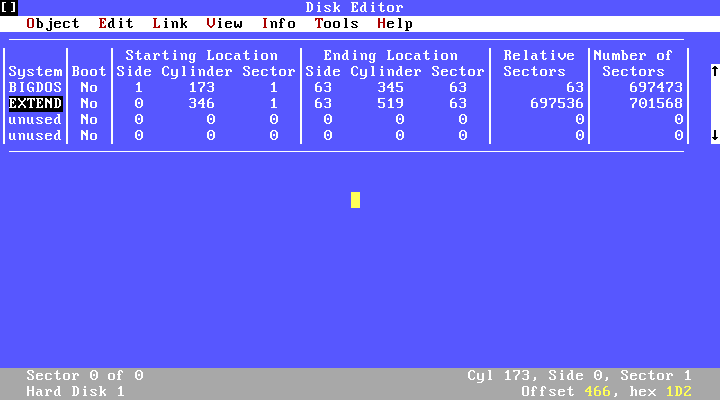
When I checked the disk with disk editor, there were 520 cylinders on the disk (I used the old version disk editor for this example, without any specific reason). The first partition ends at the cylinder 173. So, the primary partition is fine. Second partition is listed as EXTEND and there is another partition table at the address CHS(173,0,1). By pressing Enter while EXTEND is selected, will show that sector formatted as partition table.

This partition table looks like the previos one, at the address (0,0,1) but they are not same. In the lower right corner of the screen, I can read the address (173,1,1), so I am not reading MBR obviously. When I switch to the Hex view by pressing F2, there is no MBR code in this sector but a partition table and sector signature. The first entry of this partition table is a partition starting at (173,1,1) and ending at the cylinder 346. Second entry is another extended (EXTEND) partition right after where the previous partition ends. When you select this extended partition in editor and press Enter, another partition table without boot code can be seen at CHS(346,0,1) sector. In this partition table, there is a partition starting from (346,1,1) and ending at the end of the disk. As can be understood, the extended partition is a structure that contains the logical partitions inside it and keeps their information in a linked list (sort of) of partition tables.
As far as I know, there is no reason, in theory, for extended partitions not the be bootable but the code in MBR needs to search for the active partition among the extended partitions, if there is no active partition in the main table. This means an increase in the size of the code, which actually has to be limited to 512 bytes. I am not sure whether this is something undesirable for the standard makers or if there is some other reason. Further examples can be found in Wikipedia in
Extended Boot Record article.
How Does MBR Code Work?
To examine their MBR codes, I booted both machines that I set up so far, with DSL and saved their MBR code with the following command:
dd if=/dev/hda of=mbr.bin count=1 bs=512
The same command on a machine with a recent Linux distro would be;
dd if=/dev/sda of=mbr.bin count=1 bs=512
Then I disassembled these outputs with the following command;
objdump -M intel -D -b binary -m i8086 --adjust-vma=0x7C00 mbr.bin > mbr.asm
on a linux machine.
In order to keep the article short, I uploaded disassembled outputs of
DOS6.22 MBR and
FreeDOS MBR to my Google drive with comments, instead of examining the code line by line here. Both codes are same, in general: After setting the stack pointers, the code copies itself to the address 0:0600h in DOS and 1FE0h:7C00h in FreeDOS. Because boot sector code, which will be loaded right after must be placed in the same 7C00h address. As I previously mentioned, there is no difference between the boot sector and MBR codes from the BIOS perspective. The task of the BIOS is to read the first sector of boot media to 0:7C00h, check 55h AAh bytes at the end and jump to this address. If the boot media is floppy, the boot sector is read to this address since there is no MBR to read.
In DOS, it is checked whether there is one and only one 80h flag as bootable flag in partition table. However, in FreeDOS, the boot sector, corresponding to the first partition table entry with the highest bit of the bootable flag is 1, is read. If the boot sector could not be read, a "read error" is thrown. There is no other control than that.
Regarding to disk reading, DOS tries to read the boot sector, whose CHS address is got from the partition table entry, five times using a counter kept in DI register. If the boot sector cannot be read at the fifth time, it gives the error "Error loading OS". There is no LBA support in DOS MBR code. On the other hand, FreeDOS checks for LBA support first. If it is supported, the code reads the boot sector using the DAP, stored in 7CCDh. If unsupported, almost the same code like DOS MBR runs. Signature check is done after sector is read (in FreeDOS, this check is on the return of the disk read function) and the program jumps to 0:7C00h.
In fact, I must discuss GRUB, GPT and UEFI as a continuation of this topic but since UEFI is a technology that I do not know very well, I will summarize them in a future article. Although what I have discussed in this article is the technology of 1980s, the code that is run today (unless UEFI is not used), is the same except minor differences of course. I have finished MBR, so far. In the next article, I am going to discuss the next step, the boot sector.