Hi there. A comment from a valuable friend to the previous serial thermometer article gave me the idea for this article. As you know, computers with serial port are no longer available. If I want to read the temperature data to my mobile phone, is there an app to read it installed in my phone? Maybe yes, there are applications which can read raw data from Bluetooth (BT) in PlayStore. How safe are these apps? Why does an applications whose only job is to send / receive data to/from BT wants to access my camera or my mic?
Since BluetoothSPP app, which I was using on my first smartphone, was not compatible with the Android version that I am using on current phone, I wrote a MobileApp for my BT remote controlled car. The only thing it does, is to drive the car back and forth, turn it or stop it by sending one byte messages (or characters to be more precise). For this app, I didn't need to learn Android programming from the scratch thanks to MIT App Inventor (AI2). With AI2, it is possible to develop MobileApps by dragging and dropping controls without writing a single line of code. Maybe it's not perfect tool, but ideal for developing something fast (prototyping). Is it safe? Well, I have not personally tested its security, but it seems unlikely that an institution like MIT will develop a platform that possibly contains malware. Moreover, if such a platform with ~60K active users per day (>8M users in total) had security issues, we would have most likely heard that immediately.

I will use the setup described in the first option in the link above. First, I installed the app to my phone. It is stated that the computer and the phone must be connected to same WiFi network. My computer is connected with cable and everything works fine. So, I must correct this so that they has to be on same subnet.


1- Since I will not connect to another device, I have to set the ListPicker1 invisible:
Before moving on to AI2, I will shortly explain the hardware I use and the software running on Arduino. By the way, in this article, I just wanted to show the proof of concept. This app works only "well enough", it is not perfect in terms of design because design is not my specialty. It would be simpler if I had designed the circuit
with a microcontroller instead of Arduino, but let this be a topic for another article (if I ever can).
Parts List
Arduino Uno
Arduino Bluetooth Shield
2x 4.7K Resistors
DS1621 IC
Breadboard
Dupont Jumper Wires (about a dozen)
Setting Up the Circuit
I based on the circuit, I have described in I2C with Arduino article and I added Keyes Bluetooth module to the circuit. Original schematic is below:
 |
| DS1621 Termometre |
The BT module has 4 pins (figure right). RxD and TxD pins are connected to Arduino's D3 and D4 pins respectively. There is no special reason to do exactly so, they can be connected to any data pin by making necessary code changes. Remaining two pins are Vcc and GND, obviously.
 pins are connected to Arduino's D3 and D4 pins respectively. There is no special reason to do exactly so, they can be connected to any data pin by making necessary code changes. Remaining two pins are Vcc and GND, obviously.
 By the way, a small donation is asked since about a year, to download Fritzing. The source code is still freely available on github for those who want to compile it. And I am not sure if it can be compiled on Windows without any problem. The files have not yet been deleted from the fritzing.org server but there are no links available to the older versions on their website (they can be found with some search). Older versions like v0.8.5 and v0.9.2 are available in Linux Mint and Fedora repos. The amount of donation is just 8€, by the way. It is not very expensive at all. Personally, I did not pay, as it is already installed in my computer (although it is a bit old), but I can choose to pay in future. Installation files can also be found on third party sites, but I think those files are not really safe.
The whole circuit is simply on the image below:

I copied the code running on Arduino, from the I2C article and added about 16 more lines of code for BT connection. To connect BT module to a different pin, to const definitions at the tenth and eleventh lines has to be changed.
/* DS1621 temperature sensor interfaced by Arduino
*
* I2C ID will be 0x48 if A0 = A1 = A2 = GND
*/
#define DS1621 B1001000
#include <Wire.h>
#include<SoftwareSerial.h> // For BT module
const int BTRxD = 3; // BT RxD Pin
const int BTTxD = 4; // BT TxD Pin
// Define a SoftwareSerial object
SoftwareSerial Serial1(BTTxD, BTRxD);
void setup() {
// I2C initialization
Serial.begin(9600);
Wire.begin();
Wire.beginTransmission(DS1621);
Wire.write(0xAC); // Send Access Config command
Wire.write(0x02); // Write 02 to config register.
// Output polarity bit = 1 => Active High
delay(10);
Wire.beginTransmission(DS1621);
Wire.write(0xEE); // send "start convert" command
Wire.endTransmission(); // Stop bit
BluetoothInit();
}
void BluetoothInit() { // Bluetooth initialization
Serial1.begin(9600);
Serial1.flush();
}
void loop() {
float degree;
byte SH, SL, X;
char buffer[8]; // BT buffer
// SH: High order byte of temperature
// SL: Low order byte of temperature
Wire.beginTransmission(DS1621);
Wire.write(0xAA); // Send "Read Temperature" command
Wire.endTransmission();
Wire.requestFrom(DS1621, 2);
// After sending "read temperature" command
// request two bytes from IC for temperature
X = Wire.available();
if(X >= 2) { // if 2 bytes were received
// SH contains the integer part of the temperature
SH = Wire.read();
// SL contains 0x80 for 0.5 degree celcius
SL = Wire.read();
}
delay(500); // read the temperature from BT and send two times per second
degree = (float)SH + float(SL) / 256.0;
dtostrf(degree, 2, 2, buffer); // convert degree to string
Serial.println(buffer);
// Send the data in buffer to BT
Serial1.println(buffer);
Serial1.flush();
}
This program simply retrieves the data from the temperature sensor, converts it into degrees as float, then the float value is converted to string and it is sent to both serial port and BT, which I defined as Serial1 object. I compile this code and send it to Arduino. The light on the BT module will flash becuase no BT clients are connected yet.
Designing the App using MIT App Inventor2
In this chapter, I will explain how the MobileApp is developed. First steps to configure AI2 are explained at https://appinventor.mit.edu/explore/ai2/setup. I need;
1- to go to http://ai2.appinventor.mit.edu/ and login with google account. I don't really like that this page is served in HTTP instead of HTTPS but there is nothing to do about this. It would be also nice if we could open our local account on this site instead of google account.
2- to download and install MIT AI2 Companion app from PlayStore. As far as I know, AI2 does not support iPhones. It is still possible to develop Apps on WebUI without any phone and AI2 Companion, but AI2 Companion is required to try the developed application on the smartphone.

Now I click to
"Start new project" and create one. I named my project ThermoBT. MobileApp will be named after the project name. The project will be opened right after it is created. If not, it can be opened from "My Projects" menu. After the project is opened, click "Connect -> AI Companion" as shown on the image right. Then a QR code and password will appear on the screen. Now, when I open the app on my phone and scan the QR code, AI2 connects to my phone. From now on, everything I do on web interface, will immediately appear on my phone.
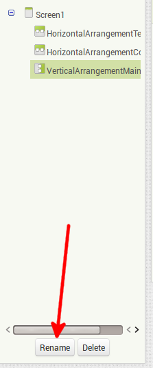
On the left side of the web interface, there are components needed to build a GUI for the app. When these components are dragged and dropped onto the  virtual phone on the screen, they are placed into the list on the right side of the screen (Components menu). To align the components to be added, I need to place some "Arrangements" from Layout tab. These can be thought as invisible tables. I add two "HorizontalArrangement"s, one below the other and one "VerticalArrangement" under two "HorizontalArrangement"s. I change their names to distinguish them when I use the same component more than one. I renamed the top "HorizontalArrangement" to "HorizontalArrangementTemp", the middle one to "HorizontalArrangementControls" and the bottom one to "VerticalArrangementMain". There is a "Rename" button in the "Components" menu. Finally, I place another VerticalArrangement in VerticalArrangementMain and rename it to VerticalArrangementSub. I used this youtube video below to understand how to use Arrangements. By the way, youtube is the best resource to learn AppInventor:
 virtual phone on the screen, they are placed into the list on the right side of the screen (Components menu). To align the components to be added, I need to place some "Arrangements" from Layout tab. These can be thought as invisible tables. I add two "HorizontalArrangement"s, one below the other and one "VerticalArrangement" under two "HorizontalArrangement"s. I change their names to distinguish them when I use the same component more than one. I renamed the top "HorizontalArrangement" to "HorizontalArrangementTemp", the middle one to "HorizontalArrangementControls" and the bottom one to "VerticalArrangementMain". There is a "Rename" button in the "Components" menu. Finally, I place another VerticalArrangement in VerticalArrangementMain and rename it to VerticalArrangementSub. I used this youtube video below to understand how to use Arrangements. By the way, youtube is the best resource to learn AppInventor:
Now, I go back to the components list on the left hand side and place two "Labels" side by side from "User Interface" tab into "HorizontalArrangementTemp" which is at the top of the virtual phone screen. Then I click either to Label1 on the virtual phone or to its corresponding entry in the component list and locate the "Text" property in the rightmost "Properties" section and change it to "Temperature: ". Similarly, I remove Label2's Text field blank and set the height of the Label2 to 50%.

Finally, I click Width of HorizontalArrangementTemp's properties, select "Fill Parent", and click OK. So, I am done with this box.
Then, I drag a "CheckBox" and a "Button" next to each other, into the second arrangement. Of course, everybody is free to design as they wish, but paying attention to the naming is needed while writing the code. I rename the button object to "ButtonReadTemp" and change its text to "Read Temperature". I do not change the name of the check box object but change its text to "Read automatically". After clicking "Width" property from "HorizontalArrangementControls" setting it to "Fill Parent", I am done with this box, too (below).

Now, from the properties of VerticalArrangementMain, I assign "Center: 3" to "AlignHorizontal" and "Bottom: 3" to "AlignVertical" property and I select "Fill Parent" for both "Height" and "Width" properties. VerticalArrangementSub (inside), falls to bottom middle. I set its "AlignHorizontal" property to "Center: 3" and insert a ListPicker and a button object. The placement sequence does not matter for these two objects. I change the button text to "Disconnect from device" and the text of ListPicker to "Select Bluetooth device". After that I am done with this box, too.
From the components list on the left, I drag "Clock" from the "Sensors" tab, drop it to the phone and drag "Bluetooth Client" from the "Connectivity" tab drop it to the phone, too. These are invisible controls. I click to Clock from the components list, turn the TimerEnabled property off and set TimerInterval to 500. This means clock will be triggered every 500ms. Once everything is done, the screen should look like this:

There is no need to display temperature related components or "Disconnect" button to the user if the app is not connected to a BT device. Likewise, if the app is connected to a BT device, there is no need to show device list, either. Therefore, I go to the properties of HorizontalArrangementsTemp, once more and uncheck the Visible box at the bottom. I do the same to HorizontalArrangementControls and Button1 (Disconnect). Now, when the app is started, it only shows the device selection button. Other components only appear if BT connection is established. So far, the design is completed.
Coding with MIT App Inventor 2
I think the best feature of AI2 is, being able to create procedures with colored pieces of code lines, like playing lego, instead of writing code as we understand. In this section, while creating BT related controls, I used the video below:
To create procedures, I press "Blocks" button at the rightest side of the top green bar. I will program first ListPicker1, to show the list of BT devices when pressed. To do this, I select ListPicker1 from the list on the left and drag the ListPicker1.TouchDown block from events list to the white area. Then again, I drag "set ListPicker1.Elements to" block from the events list of ListPicker1 to the workspace. Finally, I place "BlutetoothClient1.AddressesAndNames" (light green) from the list of BluetoothClient1, to the left side of dark green "set ListPicker1...". After one piece is interlocked to other one (like a jigsaw puzzle piece), I attach them into the fitting place next to "do" statement in brownish "when ListPicker1.TouchDown" block.
I previously wrote that whatever is added on the web interface of AI2, is reflected in the application, seen on the phone, simultaneously. The same applies to codes. The codes are also sent to the phone at the same time when adding / deleting a block etc. Previously, I had connected the Arduino to my computer and wrote the code to the chip. When I return to my phone and select "Select Bluetooth device" in the app, I am developing, it will list BT devices (of course BT needs to be enabled on the phone) but even though the devices are listed, the connection code is not written yet.
I will use the ListPicker1.AfterPicking event to connect to the device, and inside it, I place a "if ... then" block from Built-In -> Control. Then, I add purple colored .Collectaddress function block from BluetoothClient1 functions next to the "if" block, I just placed and finally, I add ListPicker1.Selection value (light green) next to it. "connectaddress" function will be called and if the function succeeds, the block next to it will be executed afterwards. I will not call any BT handler or anything else related with BT within "then" block, but I need to make some visual adjustments.
set ListPicker1.Visible to false


2- I have to set the Disconnect button visible:
set Button1.Visible to true
3- I have to set Arrangements visible:
set HorizontalArrangementTemp.Visible to true
set HorizontalArrangementControls.Visible to true
4- In order not to read the temperature automatically at first:
set CheckBox1.Checked to false
True and False values can be found in Built-In -> Logical. And dark green boxes can be placed vertically like this:

Now, selecting HC06 (Arduino BT module) from BT device list in the phone app, will cause the BT module light stop blinking because the phone is successfully connected to BT module. But when I press "Disconnect" nothing still happens because Disconnect is not implemented yet. The disconnection procedure should be the opposite of the connect function above. BluetoothClient1.Disconnect needs to be called and I will set the visible objects invisible, which set visible above and vice versa. To keep the article short, I only give the related code block:

So far, the application also disconnects. Now it is the time for the most important procedure: reading data from BT. I will use Click event of ButtonReadTemp. Before reading any data, I have to check that BT is still connected and there is data available in the buffer. This step is important because even after the initial connection is made, the device might be physically disconnected (or unavailable, for example the device went out of range). Therefore, I add an "if ... then" block into the ButtonReadTemp.Click event block. Then I place an AND logical conjuction block from Built-In -> Logic. The first condition is BluetoothClient1.IsConnected. The second condition is whether some data is available in the buffer for reading. To check this second condition, a mathematical comparison is needed which is actually the equal block from Built-In -> Math. After placing this, I change equal to "greater than". I place BluetoothClient1.BytesAvailableToReceive to the left hand side of the inequality and 0 (zero) to the right hand side. Zero is available in "Math" section of the list.
When all these conditions are met, the data will be read from BT and written to Label2. In the end, the ButtonReadTemp will look like this:

When I go back to the app and press "Read Temperature" button, if the app has been connected to the module for a long time without reading any data, temperature values accumulated in the buffer, will fill the screen out. That is the reason why I limited the height of Label2 to the half of the phone screen. As I wrote at the beginning, I tried to quickly develop something for this project, therefore the result is not perfect.
Since the buffer is filled quickly, the best would be to read the data automatically. For this, I add a procedure to the CheckBox1.Changed event. If CheckBox1.Checked is true, then I need to enable Clock1 and disable ButtonReadTemp or vice versa. This is pretty straightforward compared to other procedures. First, an "if ... then ... else" block is required for this. This block can be either found under "Control" section, or it can be also created by pressing the blue gear icon at the upper left of an "if ... then" block and then dragging the "else" into the "if" block on the right.

Finally, if Timer is enabled, Clock object needs to do what originally the ButtonReadTemp.Click does:

To create the above procedure in an easy way, I right click on the "if ... then" block, I created for the "Read temp" button, select "Duplicate" and insert the duplicated block into the Clock1.Timer event. That's all. If this application is finished completely, I can download it as an .apk file to my phone and use it without AI2. For this, you need to click "provide QR code for .apk" from the Build menu in web interface. After the app is compiled, a link to download the .apk and a QR code containing this link, are displayed. At this step, if AI2 Companion app is still connected, you need to disconnect to scan new QR code (using Connect -> Reset Connection or by closing and reopening the app on the phone). When I reopen AI2 Companion and scan the QR code -if the security settings allow apk installation on the phone- the app will be installed and can be used independently after granting requested permissions.
The application, created, can be downloaded to the computer using "Export selected project (.aia)
to my computer" under "My Projects" menu. The project file, I created, in this article can be downloaded from here.